 |
|
|
|
Damp Proof Remote Telemetry Unit , HV Switch Controller Electric Feeder Unit
Product Details:
Payment & Shipping Terms:
|
| RrentLatching Cu: | 0.010-10*In;Starting Value For Large-current Latch-up Protection | O->I Switching: | ON/OFF ;Enter Or Exit Of Zero-sequence Reclosing Function, ON As Enter, OFF As Exit |
|---|---|---|---|
| O->I1 Time: | 0.30-600.00S Interval Of Single-shot Reclosing | O->I Lockout: | 0-2 0:OFF 1: After Acceleration 2:Accelerate |
| Lockout Delay: | 0.00-600.00S Post Acceleration Time | IN>Amp Switching: | 0-2 0:OFF,1Alarm,2:Tripping |
| High Light: | feeder remote terminal unit,dsp digital signal processor |
||
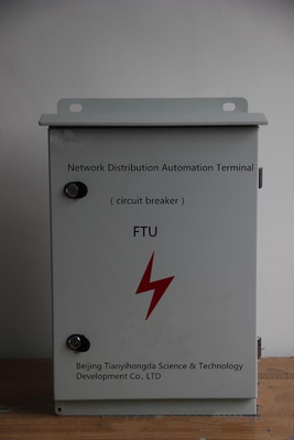
new HV switch control device equipped with wide range of adaptation and damp-proof
The case of this device is stainless steel with sprayed powder. It is beautiful and has sufficient rigidity and excellent anti-rust performance. The following picture is the overall structure and layout of the device.
reparation before Installation
Because the installation positions and methods are different, the users shall prepare the installation fittings by themselves before installation according to the sizes of mounting holes and the installation methods.
Note: Please refer to the installation dimension drawing attached to this manual for the detailed sizes of mounting holes and installation methods.
Fixing of Upper Rod
The outer door the device shall be closed while fixing the upper rod. Make sure to prevent the case from impact and collision of external forces. The installation shall be secure and reliable.
n:'yes';font-family:'Times New Roman';font-size:10.5000pt;mso-font-kerning:1.0000pt;" >
Note: Please refer to the installation dimension drawing attached to this manual for the detailed sizes of mounting holes and installation methods.
The device has powerful integration and expansion capacities. It not only satisfies the functional requirements of the current distribution network automation, but also provides sufficient expansion space for further improvement and upgrading. It boasts of the following features:
Reliable and Stable Operation
The device inherits the rich R&D and onsite operation experience of our company in relay protection devices, measuring and control devices, communication devices and distribution network automation. Many relevant aspects are taken into account and various technical methods are adopted. The terrible operating conditions for the device are fully taken into account in the design. The device features excellent electromagnetic compatibility, low power consumption and a wide range of operating temperature. It is shockproof, moisture-proof, lightning-proof and of great reliability and stability
Adequate and Practical Functions
It boasts of all the functions required for the present relay protection and can carry out on/off combination according to the practical requirements. It can fulfill the “four-remote” (remote signaling, remote metering, remote control and remote regulating) functions through the local serial ports and realize the remote communication function by different optional communication modes.
Easy to Expand
The hardware and software platforms of the device are designed to be equipped with the unified interface and expansion margin to facilitate future expansion and technology upgrading, in order to guarantee a longer service life of the device.
Easy to Maintenance
It can make self-diagnosis and self-recovery as it is equipped with large-capacity non-volatile memory that can keep a detailed historical record and will not cause data loss even under power failure. Its interface is extremely user-friendly as it adopts LCD display interface where information is displayed in multi-layer menus in Chinese.
Date Storage
It is equipped with large-capacity non-volatile memory that will not cause data loss even under power failure and can keep a detailed historical record.
Atmospheric pressure: 66kPa~108kPa.
Operating environment: no explosive and flammable materials, no air or conductive dust which will damage the insulation and cause metal corrosion, no serious mold and no severe vibration sources, with measures to defend against rain, snow, wind, sand, dust and static electricity.
![]()
Remote metering area: It is at the right of the main interface, indicating the remote metering data collected currently. The table for remote metering symbols is as follows:
| Symbol | Representing remote signaling | Symbol | Representing remote signaling | Symbol | Representing remote signaling | Symbol | Representing remote signaling |
| Ia | Current of Phase A | Ua | Voltage of Phase A | I | Current | ||
| Ib | Current of Phase B | Ub | Voltage of Phase B | H | Frequency | ||
| Ic | Current of Phase C | Uc | Voltage of Phase C | P | Active |
Fax: 86-10-63330700
-
Wireless Transmission 50HZ Power Distribution Terminal For Monitoring Fault
-
Power Feeder Remote Terminal Unit , Status Data Din Rail Terminals By Gprs / 3
-
Automatic Power Distribution Terminal For All The Protections 1.5 Times Fixed Value
-
Strong Stability Power Distribution Terminal For Overhead Line Zero Sequence Reclosing
-
Counter Current Value Remote Control Terminal , HV Switch Control Remote Control Feeder
-
Fault Detection Power Distribution Terminal For Transmitting Measured Data


