 |
|
|
|
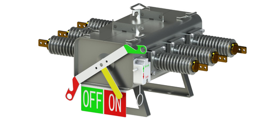
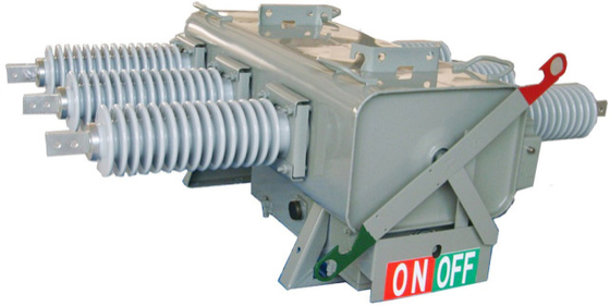
Electrical SF6 Gas Insulation Pole Mounted Switch , 3 Phase Linkage High Voltage Switch
Product Details:
Payment & Shipping Terms:
|
| Material: | Stainless Steel | Design: | Segmented Application |
|---|---|---|---|
| Operated: | Manually Or Remotely | Switch Housing: | Welding Seal |
| Casing And Shell: | Rubber Ring Seals | ||
| High Light: | high voltage switch,circuit interrupter switch |
||
high voltage electrical SF6 Gas Insulation three-phase Linkage pole mounted switchHigh with pressure wireless communicat
Construction of switch
1. Manual handle.
FWX operate safely with a high-voltage insulation rod, its structure can complete one-time operation on or off.
![]()
2 Manual locking device
During blackout operation, to prevent the wrong operation of the switch.During the operation, pull down the manual mechanical locking device and pull the ring to lock the switch mechanism in the position of "on" or "off", and the switch can no longer be operated when the switch is closed or opened. At the end of the operation, push up the manual mechanical locking device pull the ring to unlock the switch mechanism, the switch can be operated again. Ensure the reliability and safety of the operation.
![]()
Manual locking device
3 Contact position indicator
Standing on the ground, it is easy to see the color-marked position indication of the switch.(Green–Off;Red–On).
4 Low pressure locking device
When the pressure drops to 0.02~0.04mpa, the automatic locking device is equipped to make the switch lock, which cannot be operated manually or electrically. At the same time, there are red alarm signs to alert.
![]()
5 High pressure relief alarm device
In order to prevent the vessel from cracking when the gas pressure rises sharply due to the internal abnormality of the switch, a high pressure explosion proof and pressure relief device is specially installed. Pressure relief film actuated at 0.4mpa - 0.6mpa pressure,releasing internal pressure.High pressure explosion-proof pressure relief device is installed in the opposite direction of the hand handle to avoid pressure release film rupture endangering operator and public safety.
![]()
In /out line connection diagram
![]()
Terminal connection indication
4. Product installation
① Pre-installation confirmation
Opened the packing, check the packing list and product parts to confirm if match.;
Check the appearance of the switch bye eye to confirm whether the porcelain sleeve, closing / closing indicator, manual handle, gas pressure gauge, etc., are damaged or abnormal; When there is a gas pressure gauge in the body, read the gauge to confirm that it is within the normal gas range (standard pressure ±0.01MPa);
Manual operating closing / opening 5 times;
After the above procedure, the installation begins when there is no abnormal;
※After open the package, please do not lift the porcelain sleeve or handle when handling the switch. Be sure to use a hook or handle (above the body), abnormal performance will occur when handling with a porcelain sleeve or handle.
②Installation essentials
Install switches in the following order and essentials.
Install upper and lower hoops on the poles.
Please refer to the assembly diagram below to install the bracket.
![]()
Mounting bracket drawing
Insert the bolt on the hole above the switch
Assemble mounting bracket and galvanized plate, cover on top of switch, flat pad and screw fixing.
Use the hook on the top of the switch to lift the switch to the installation position.
After adjusting the level of the switch body, the upper hanger hoop, the lower hanger hoop firmly fixed with the mounting support.
Install the control box on the pole;
Connect the ground wire to the ground terminal of the switch and control box;
Switch and control box are connected with control cables;
Confirm that the closing / opening indicator is normal.
Use the closing / opening button of the control box to operate the closing / opening about 5 times.
Switch hoist installation
![]()
Switch seat type installation
![]()
For more details, please contact by e-mail:bjxrqfoverseas@163.com
Fax: 86-10-63330700


