 |
|
|
|
Overhead Distribution Lines Fault Circuit Indicator , Quickly Phase Loss Indicator Short Outage Time
Product Details:
Payment & Shipping Terms:
|
| Reset Way: | Reset Itself Upon The Power Return | Indication: | Flashing And Triggering A Flip |
|---|---|---|---|
| Rust And Corrosion Protection: | Structure Part Is Made Of Corrosion-resistant Material | Wireless Data Communication: | By Sending The Fault Signal To FTU |
| High Light: | short circuit indicator,short circuit detector |
||
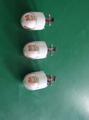
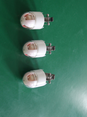
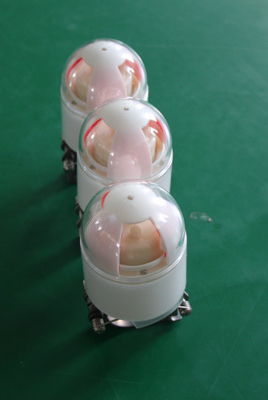
The fault indicator for overhead distribution lines for point of failure quickly and shorten the outage time
The fault indicator for overhead distribution lines is used indicating of phase-to-phase and phase-to-earth faults by determining short circuit, over-current and power features to detect faults and provide a local light indication. In addition, the indicator also has current measurement and wireless data communication capabilities, by sending the fault signal to FTU,in order to comply the function of the remote communication and the remote monitoring, to help operators to find the point of failure quickly and shorten the outage time and improve reliability.
Principle:
The fault indicator installed on the overhead lines, which clipped on each phase so that to detect current and Voltage signal in this phase using itself clipped line structure. Through the low-power chip, it completes current calculation, short circuit, ground fault detection, and through built-in low-power RF modules achieves short distance wireless communication.
After the indicator is installed, the line current has been measured . When the current meet the characteristics of the fault, the indicator immediately sends the fault current and the fault information to the nearest terminal device by the RF, while triggering a flop and flash indication.
The lineman simple follows the flashing fault indicators all the way to the first non-flashing fault indicator, thereby identify the fault location.
The terminal device receives the fault information can further upload, so master station can get useful information and determine the fault zone according to the sub-station uploaded information.
![]()
![]()
Shocks and vibrations:
a)Power frequency magnetic field test
When continuous sine waveform, 100A / m magnetic interference applied to
the indicator, it should work correctly.
b)Grip test
The downward pressure in the direction perpendicular to indicator spring is not less than 8 times the weight of the overall indicator .After fault indicator mounted ACSR, the transverse tension along a direction of aluminum wire is not less than 50N. So that, Indicator can withstand winds without falling from the line.
installation:
a) By fitting the bracket installed in the hot sticks, screw detaching sheet nut to let the sheet fully retracted into the interior of the column (ie: try to tighten the sides, leaving enough space so as not to block the indicator when installing).
b)put the indicator into the bracket , and make the spring device to hook with the indicator spring, and rotate the spring device down firmly until after the indicator spring pulled position retractor can hook, then hook the spring with retractor and pull t he spring device out. And use the same method to the other side of the same end of the indicator spring to hook retractors.
c) Aligning the overhead lines pushed up and under the pressure of the overhead lines the indicator springs are divorced from the retractor spring and stucked overhead lines firmly.
There is type test report for it, test items as following:
|
Type Test Items
|
1. appearance and structure 2.function 3. electrical device performance 4.low temperature performance 5.high temperature performance 6.alternating temperature humidity7.vibrationendurance 8.incline drop test 9. electrical device life 10. static electricity and elecro-discharge immunity test 11.radio frequency electromagnetic field radiated immunity test 12.surge impact immunity test 13. power frequency magnetic field immunity test. 14. Adjacent interference test 15.short-circuit withstand impact test 16. fire hazard test 17. power consumption test 18. protection grade test 19. gripping strength test of grip structure. |
Fax: 86-10-63330700
-
35KV Communicable Fault Circuit Indicator For Underground Cable Data Transmission Unit
-
Remote Terminal Fault Circuit Indicator , GSM / GPRS High Voltage Cable Fault Locator
-
Earth Fault Circuit Indicator , Reliable Transmitting Short Circuit Detector
-
6KV - 110KV Fault Circuit Indicator , Epoxy Resin Insulated Short Circuit Indicator


